Su carrito de compras está vacío
 
English Polski Spanish 
Buscar un manual
 

(p.Ej. AA-V20EG JVC, ZX-7 Sony)
PayPal 1000+ rating Secure, Encrypted Checkout.
 
Usuarios conectados
Actualmente hay 6043 visitantes online.
Productos
Información
Destacado
Inicio >> SHARP >> DV660S Manual de Servicio
 
 0 artículo(s) en Su carrito 

SHARP DV660S
Manual de Servicio


¡Twitee acerca de este producto y obtenga $1.00 de crédito en la tienda para uso!
  • Contiene diagramas del circuito
  • Descargable
  • Formato PDF
  • Manual completo
  • Idiomas: English
Precio: $4.99

Descripción del SHARP DV660S Manual de Servicio

Manual de servicio completo en formato digital (archivo PDF). Los manuales de servicio por lo general contienen diagramas de circuitos, tarjetas de circuitos impresos, consejos para reparación, diagramas de cableado, diagramas de bloque y lista de refacciones. El Manual de Servicio (a veces llamado Manual de Reparación) es usado principalmente por los técnicos.

Si tan solo quiere saber cómo utilizar su televisión, reproductor de vídeo, reproductor de mp3, etc. Quizá lo que necesita es el Manual del Propietario. Después de colocar la orden le enviaremos las instrucciones de descarga a su dirección de e-mail.

The manual is available in languages:

Not yet ready
You must purchase it first

Opiniones de los clientes
No hay comentarios de productos.

TEXT_PDF_SNIPPET
DV-660S DV-660H

6. DISASSEMBLY AND REPLACEMENT OF MAIN PARTS
6-1. DISASSEMBLY
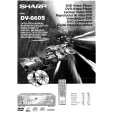
1. Remove five screws (A), and remove the cabinet. Note: When assembling it, tighten the screws in order of 1 - 2 . (Because the set may rise a little by tightening the screws.)
(A) x2 1 Top Cabinet (A) 2

(A) x2 1

2. Remove two screws (B). 3. Remove one screw (C). 4. Release the hooks of the front panel at two places on both sides and at three places on the bottom, and slide the front panel toward
(B) x2 (F) x4 (D)

you. 5. Disconnect the connectors (D) and (E). 6. Remove four screws (F) which installs the mechanical unit.
(E)

Hook Front panel (C) Hook
(H) (J) Main PWB (G) (L) (S) (L) (M) x7

7. Disconnect the lead lines (G) and (H) and (J) from the main PWB under the mechanism. 8. Remove two screws (K) on both sides of the terminal angle frame. 9. Remove three screws (L) which install the terminal PWB. Mechanism 10. Remove seven screws (M) and one screw (N) which install the
(S)

terminal block. 11. Remove three screws (P) of the display PWB. 12. Remove two screws (Q) of the decorative leg. (P) x3 13. Push out the middle pin (R) of the setting leg in the direction opposite to insertion. (Two places) 14. Remove two screws (S) which install the main PWB under the mechanical unit.

(N) (K) x2 21-Pin Euro-SCART PWB (L) (R) x2 Terminal PWB

Display PWB

(Q) x2

(W)

15. Remove three screws (T) which install the volume PWB of the front panel. 16. Remove three screws (U) which install the operate PWB. * The spacer and insulation seat under the indication tube of (V) and (W) are bonded with both-side sticking tape. 17. Remove one washe (X) and one nut (Y) which install the shuttle knob.

(V)

Volume PWB

(T) x3

(U) x3

(Y)

Operate PWB (X) Shuttle knob

6-1

Quizás también quiera comprar

$4.99

DV660S SHARP
Manual de Usuario

Manual del propietario completo en formato digital. El manual estará disponible para descarga como …
>
Parse Time: 0.22 - Number of Queries: 99 - Query Time: 0.06